
Support
FAQs
Any questions? Doubts? Suggestions? Or specific circumstances which are not solved via the FAQ? Please contact us by clicking here.
How a magnetic lock is made of?
Primarily of steel, copper and resin.
- The steel must be of first quality in order to:
- To pass on most of the magnetic flow
- Not to become itself a permanent magnet (no magnetism residual)
- To be particularly protected from corrosion.
- Aesthetically appearance
- But specially to avoid the drop of holding force.
- The winding copper must be of OFC type to create a maximum magnetic field in the steel.
- The resin must be stable, must resist to important temperatures variations, without losing its quality (must not break, soften or be inflammable).
How to carry out a successful, fault-free installation?
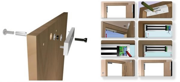
Fitting a magnetic lock is quite simple, and the two illustrations below provide simple explanations on the order of assembly that must be observed.
- Start by mounting the armature plate 1 (do not screw too tight!), 2 and then fit the lock.
- The “tricks” of a Pro: After mounting the armature plate, provide power to the lock with a 9-volt battery. It will stick to its armature plate and you will have both hands free to pencil in the contours of the lock on the doorframe.
- After checking that the assembly is working correctly, unscrew the armature plate slightly and introduce a drop of thread-locking compound into the thread of the armature plate screw.
- Check for the last time that the fastening of the armature plate is flexible.
- Be rigorous from the start and your installation will work perfectly.
- For wiring, please refer to the connections section.
The characteristics of our HQMAG products are represented in a standard label, in compliance with the norm the EN 13637, chap 7.
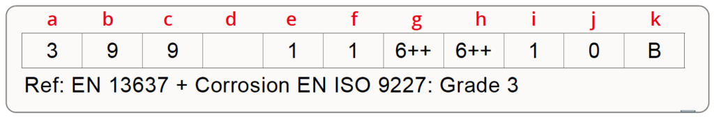
a = High frequency of use
b = Reliability: 1,000,000 cycles
c = Weight of the door:> 200 kgs
d = Fire / smoke suitability standard EN1634-x
e = Complies with the personal safety standard
f = IP protection min: IP43 – EN1670 grade 3 – damp heat test 12h + 12h
g = Holding force from outside: 15000N
h = Inner holding force: 15000N
i = Time delay: t1 (adjustable 0 to 8 seconds)
j = Unauthorized exit mode: No function unless CMC
k = Configuration of the emergency locking system: Other system.
Why does HQMAG indicate holding forces according to grades and what does this correspond to?
The grades regarding the holding forces are official and recognized hierarchical classification allowing for qualitative discrimination. Then, the quality and reliability of the HQMAG locking products are determined and differentiated by the official grades described in European standard EN 13637. This VOLUNTARY European standard relating to SYSTEMS for managing evacuation routes, in its Chapter 7 describes the specific characteristics of the “locking” component and is used as a ground for our classification. This information is materialized on each of our products via a standardized self-adhesive label showing by grade the different performance of the product, including its holding force.
Point 7.2.8 of this standard « Security/Holding force – from outside (7th character) » lists grades/holding forces as follow:
Grade 2: 1000 N
Grade 3: 2000 N
Grade 4: 3000 N
Grade 5: 5000 N
Grade 6: > 5000 N
Due to the disparities in quality on the market and the exceptional quality of the HQMAG electromagnets for which the holding force on certain references is much higher than what is provided for by the standard, we have gone further than the standard by qualifying the grades such as follows:
Grade 2 (≲ 1 000N )
Grade 2+ (≲ 1 800N )
Grade 3 (2 000N )
Grade 3+ (≲ 3 000N )
Grade 4 (3 000N)
Grade 4+ (4 000N )
Grade 6 (≲ 5 300N )
Grade 6+ (6 800N ~ 7 500N)
Grade 6++ (15 000N)
This classification allows you to have a clear view of the performance of the product you purchase from HQMAG. Do other brands on the market offer you the same transparency? This is a question that is asked and answered in the white paper available through the following link: https://www.hqmag.eu/quality/
The armature plate is too tight.
This is a classic error in the first installations. The fitter is concerned that the mature plate may come loose and tightens the screw to the point of crushing the rubber washers and locking up the assembly. The door has an angular movement that can only be offset at the end of its travel with the flexibility of the armature plate. The more flexible the armature plate is, the better the system works.
The voltage at the terminals of the lock is too weak:
This is another classic case of fitters starting out on lock fitting. The magnetic locks must be supplied with power of at least 12V DC or 24V DC. If this voltage is lower at the terminals of the lock, the pulling force will be weaker and the signalling will not work correctly. Attention: The locks are delivered from the factory configured at 24V DC. If you use a 12V DC power supply, consider changing the choice of voltage.
Holding force reduced.
Possible cause: Bad physical contact between armature plate and magnet
surface. Solutions: Make sure than surface contact is cleaned and well aligned with the armature plate.
There is a delay in door release when power off.
Possible cause: The power switch-off is disturbed by the power supply stabilization. Solution: The power cut must be done between the PSU and lock. Not at the AC input of the PSU.
Electrical connections. How to make sure they work correctly
Connecting a magnetic lock is child’s play. However, it is a good idea to carefully read the electrical concepts below:
- The power supply must be at least 12 to 24 volts DC (+ 20% is acceptable)
- This voltage is measured at the lock terminals, not at the power supply terminals
- An electrical cable creates voltage losses proportional to its length and inversely proportional to its section, as explained below:

The basic formula:
Rc: Resistance of the cable
φ: Specific resistance determined by the cable type. (For copper, 0.0175 ohms)
L: Length in metres (Attention: there are 2 wires, so do not forget to multiply by two)
S: Section of the cable in mm²

And Ohm´s law:
R: Resistance (ohms)
U: Voltage (volts)
I : Current (amperes)
Example:
Three magnetic locks are fitted 25 metres from the power supply. They are supplied at 12 VDC and consume 500 mA each. The cable has a section of 0.5 mm².
We therefore have a cable length of 50 m (there are two wires) and overall consumption of 1.5 A (1,500 mA).
A) Calculation of the cable resistance:
R = (0,0175 x 50) / 0,5 = 1,75 ohm
B) Calculation of the voltage drop:
U = 1,75 x 1.5 = 2.62 volts
A lock must have at least its nominal voltage at its terminals. In this case, 12 VDC. Since we know that the cable voltage will fall by 2.62 volts, we must adjust the power to at least 14.62 volts. Or preferably, use a cable with a greater section.
Is it working correctly?
Two cases may cause poor operation:
- The backplate is too tight: This is a classic error in the first installations. The fitter is concerned that the backplate may come loose and tightens the screw to the point of crushing the rubber washers and locking up the assembly. The door has an angular movement that can only be offset at the end of its travel with the flexibility of the backplate. The more flexible the backplate is, the better the system works. (See fitting the backplate)
- The voltage at the terminals of the lock is too weak: This is another classic case of fitters starting out on lock fitting. The magnetic locks must be supplied with power of at least 12 VDC or 24. If this voltage is lower at the terminals of the lock, the pulling force will be weaker and the signalling will not work correctly. Attention: The locks are delivered from the factory configured at 24 VDC. If you use a 12 VDC power supply, consider changing the choice of voltage.